/
/  |
|
 /
/  |
|
|
|
|
|
|
|
CAN bus cable
|
| Die Verbindung zwischen den
einzelnen ZIMO Komponenten erfolgt via dem CAN
Bus.
Der CAN Bus hat einen symmetrischen elektrischen Aufbau. Wenn CAN
L die Polarität ändert geht auch CAN H in die andere Richtung.
Dadurch erreicht man doppelt so hohe Signalspennung was eine höhere
Unempfindlichkeit gegen Störspannungseinstrahlung sichert.
|
|
Interconnect between ZIMO
modules is done via a CAN bus.
The CAN bus has a symmetric electric layout. When CAN L changes
polarity CAN H does as well. This gives double voltage between the
two wires. This results in a more reliable data transmission.
|
| ZIMO verwendet 6 polige
RJ11 Stecker. Diese kann man sehr leicht selbst durch aufcrimpen der
Stecker auf ein flaches Kabel herstellen. |
|
ZIMO uses 6 pin RJ11
connectors. The can be easily made onsite by crimping them on flat
cables. |
|
|
| Da das ZIMO System mit
"nur" etwa 100kHz am CAN Bus kommuniziert, ist die
Kabelqualität kaum von Bedeutung. Die symmetrische Auslegung des
CAN-Buses macht das System sehr unempfindlich gegen
Störeinstrahlungen.
Die verwendeten 100kHz sind noch immer bedeutend schneller als
die sonst üblichen 2400 bis 19200Baud diverser anderer Hersteller!
Die Bandbreite ist von Bedeutung zur schnellen und
Verzögerungsfeien Kommunikation zwischen den Modulen und der
Zentraleinheit MX1 und dem Computer |
|
ZIMO utilizes the CAN bus
with roughly 100kHz. Every cable can cope with that frequencies. The
data is transmitted on a symmetric pair which makes it robust
against interference from outside. The electrical interface of a CAN
receiver is comparable with RS422 spec.
ZIMO's 100kHz are still much faster than other vendor's 2400 to
19200 Baud connections. This is important to have a fast smooth
dataflow from peripherals back and forward to the central unit MX1
and the controlling computer. |
|
|
|
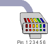
Connector
|
 |
 |
 |
 |
| 1 |
+ |
| 2 |
|
| 3 |
CAN L |
| 4 |
CAN H |
| 5 |
GND |
| 6 |
|
|
 |
 |
 |
 |
Steckerbelegung / Connector
wireing |
| Eigentlich benötigt man
nur 4 Drähte, ein 6-er Kabel ist aber leichter zu crimpen. Durch
die Steckerbelegung kann bei falscher Konfektion eines Kabels nichts
beschädigt werden. Im Fehlerfall sind (+) und (GND) nicht
verbunden, die Komponente bleibt Stromlos. CAN H/L sind im Betrieb
Symmetrisch, haben potentiell +/- wechselnd angeschlossen, und
können bei falschen Anschluss auch nicht beschädigt werden. |
|
There are only 4 wires
required, but it is much easier to use a 6way one for crimping. The
connection layout protects the equipment against wrong connection.
If a cable would be done wrong power will not be connected and
nothing happens. CAN H/L are designed to cope with the signal levels,
as they have a symmetric layout the receivers are not harmed even if
it is done the wrong way! |
|
|
|
Connector Position
|
|
|
| Am besten ist es zum
Anfertigen der Crimpstecker eine Spezialzange zu benutzen. In Europe
in der €30-€60 Preisklasse. In den USA bekommt man RJ11 / RJ45
Zangen bereits um etwa $10-$15.
Solange ich keine Zange hatte habe ich die Kontakte einzeln mit
einem flachen Schraubendreher hinein gedrückt, mit etwas Geschick
entstehen sichere Verbindungen. Bei der Schraubendreherversion bitte
auch an die Zugentlastung denken! |
|
The best way to crimp the
connectors is to use a special crimping tool. Unfortunately those
tools are expensive in Europe, they are sold for €30 to €60 in
electronic stores. In US those pliers are available for $10 to $15.
As long as I had no special tool I used a screwdriver to push the
connectors in. This works good, but needs some force. Don't forget
to push the strain relief in as well! |
Kabelfehlersuche
|
|
Debugging Cable Problems
|
| Für größere Anlagen
werden Kabel individuell angefertigt. Dabei können auch Fehler
entstehen. Die Identifikation kann schwierig werden, oder ist als
Kabelproblem nicht so leicht identifizierbar.
Langsame Reaktion des Systems auf Ereignisse, unerwartetes
Blinken der MX8 / MX9 Module, fallweises AAF in der MX2 Anzeige
können von defekten Kabeln verursacht sein. Am MX1/2000 gibt es
eine Anzeige der CAN-Bus Aktivitäten. Bei CAN_Bus -Fehlern wird da
ein "E" eingeblendet. Im Regelbetrieb darf dieses
"E" nie aufscheinen. Am ursprünglichen MX1 gibt es keinen
solchen Fehlerindikator.
Beim Fehlersuchen helfen hoffentlich folgende Hinweise:
- Nach JEDER Maßnahme das System stromlos schalten 10
Sekunden warten und dann einschalten. Schließen sie den PC ab
der wird zum BUS debuggen nicht benötigt.
- Den CAN Bus möglichst nach den Aufbaurichtlinien gestalten,
Schleifen und Gabelungen vermeiden. Zumindest zur Fehlersuche
solche Gebilde entfernen.
- Teilen sie den Bus so lange in immer kleinere Teile bis die
Fehler verschwinden
- Beim Fehler eingrenzen den Buß zuerst in der Mitte teilen,
dann vierteln, achteln usw. bis die fehlerhafte Stelle
eingegrenzt ist.
- Kabel die im Verdacht stehen Fehler zu bereiten mittels
Brückenkabel temporär ersetzen um zu testen ob das
überbrückte Kabel wirklich den Fehler verursacht. Denken Sie
daran dass auch mehrfache Kabelprobleme möglich sein können.
- Gute Kabelqualitäten verwenden, Telefonkabel, ISDN-Kabel
sind ausreichend, man benötigt kein Kat-5 Kabel, außerdem
sind die schwierig zu crimpen.
- Möglichst die CAN Bus Kabel nicht parallel mit
Leistungsverdrahtung legen. Also möglicht von Fahrstrom und
Beleuchtung getrennt. 1-2 cm Distanz reichen.
- Falls ein MX1/2000 zur vorhanden ist, es darf das Fehler
"E" nicht aufscheinen.
- STP zeigt ebenfalls CAN Probleme an (das muss ich noch
querchecken)
- Man kann auch den PC zur CAN-Bus Analyse einsetzen. Zur
CAN-Bus-Fehlerprotokollierung kann die
CANVIEW-
Software verwendet werden.
- Wenn in der Datei
STP.INI ein Eintrag "CANLogFile=<filename>"
gemacht wird, protokolliert auch STP in dieses File einige
CAN-Infos. Zum Fehlersuchen ist es hilfreich die Ausgabedatei
mit "tail" oder ähnlichen Werkzeugen
zu überwachen, das spart das ewige Neuladen in einen Editor.
Es gibt aus der Computerverkabelungstechnik Kabelprüfer für
RJ45 Stecker. Die ZIMO CAN RJ11 Stecker kann man da hinein stecken.
Manche Tester kann man "überreden" und die Belegung des
Kabels einstellen. Diese sind natürlich die beste
Test/Prüf-Variante , nur wer hat so etwas? |
|
For bigger layouts, CAN bus
cables must be made on site. Its quite common to introduce some
problems to the bus. It is quite hard to isolate them or even
identify them as bus problems.
Slow response of the entire system to events, unexpected blinking
of the LEDs on MX8 / MX9 or AAF at the MX2 display can be indicators
for a broken cable. The MX1/2k offers an error indicator in the
display. Right in the call where it displays CAN bus utilization if
there is a "E" in the display a damaged packet was
received. Unfortunately the original MX1 does not offer an indicator
for bus errors.
Eventually my list underneath might help you to isolate those
problems:
- Before verifying your measurements power cycle the system.
Please allow 10 seconds in power off state, everything is dark,
to discharge all electronics. Disconnect the PC, you don't
need it for bus debugging.
- Structure the bus as described by ZIMO. Avoid loops and forks,
at least during the debugging time.
- Segment the CAN bus into small parts to isolate the problem.
- Split the bus in the middle, then the side which caused the
problem again, and again - this is the fastest way to find the
cause.
- Use a patch cable to bridge the faulty part to verify that
you have isolated the problem. Be aware that you might have
more than one problem.
- Use good quality materials. Phone or ISDN material is good
enough. It is not necessary to use cat-5 materials. They are
actually hard to crimp and there for easily source for
troubles.
- Avoid power carrying cables parallel to the bus cable. I.e.
no DCC power or AC lightning wires around. 1" distance is
enough.
- If you are y lucky one with a MX1/2k monitor the
"E" indicator in the bus utilization display cell.
- STP also indicates CAN Bus problems. (need to verify this)
- A PC can become handy to monitor the CAN bus too. Just use
CANVIEW
to display bus activity.
- If you insert "
CANLogFile=<filename>"
into STP.INI STP logs some CAN bus
information. Use a tool like "tail" to
monitor the results file. This avoids to reopen the log file
into a editor over and over again.
Finally there are cable testers available out of the IT industry.
The come with RJ45 connectors. The ZIMO CAN Bus RJ11 can be inserted.
Unfortunately only a few of these testers can be adopted to the CAN
bus layout. If you can get hold of such an device that might be the
best method to verify your cables. |